Sony VAIO systems based on the P2B-AE shipped with either PIII
450Mhz Slot-1 processors (100Mhz FSB), or Celeron 466Mhz Socket 370
processors (66Mhz FSB). The Celerons were mounted on Asus S370-L slot
adapters, making these VAIOs perhaps the only systems ever shipped with
slot adapters as original equipment.
Owners of P2B-AE based VAIO systems found their processor upgrade
options severely limited as neither Sony nor Asus provided BIOS updates
for even Coppermine processors, let alone Tualatins. The similar
P3B-1394 also suffered from a lack of BIOS updates, in contrast to the
P2B series. However, the P2B-AE hardware appears quite capable - the
voltage regulator is able to provide processor core voltages as low as
1.3V, and the clock generator supports FSB speeds up to 150Mhz - so we
decided to determine what changes would be required in order to remove
BIOS and hardware limitations, and enable the use of Tualatin
processors and higher FSB speeds on the P2B-AE.
As expected, our attempts to boot a PIII-S 1.4Ghz Tualatin processor
mounted on a Slot-T adapter on a P2B-AE running the most recent Sony
BIOS (version 3005) were unsuccessful - the board powered up but did
not post, and our POST diagnostic card showed no activity. However,
enabling Tualatin processor support in the P2B-AE BIOS proved to be
relatively straightforward thanks to apple_rom and his BIOS patcher,
available here.
We downloaded version 4.23 of apple_rom's BIOS patcher, ran it against
the Sony 3005 BIOS, then added Tualatin microcode using our usual procedures. The
modified P2B-AE BIOS is available upon request, just send us an email if you'd like a copy.
Success! The
P2B-AE now POSTed with a PIII-S processor at 1.4v Vcore, and testing
confirmed the processor's L2 cache was properly enabled and the system
appeared to be stable. However, our 1.4Ghz processor would only run at
700Mhz (66Mhz FSB), or 1050Mhz (100Mhz FSB), depending on how the
Slot-T adapter's FSB jumpers were set.
Unlike all other P2B series motherboards, the P2B-AE has no FSB
jumpers or switches - the FSB clock is controlled by BSEL (bus select)
signals from the processor (or in our case, from the Slot-T adapter),
however the motherboard was only honouring BSEL0 (allowing selection of
66Mhz or 100Mhz FSB), but ignoring BSEL1, thereby preventing operation
at 133Mhz FSB. We therefore decided to disable FSB selection via the
BSEL0 signal, and install jumpers or switches to enable the full range
of FSB settings supported by the clock generator. We expected this
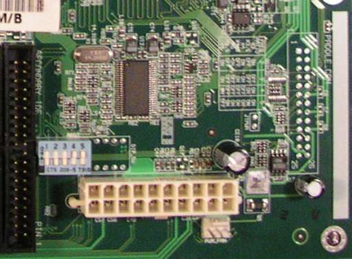
modification to be relatively straightforward, since unpopulated DIP
switch sites already existed on the motherboard, as shown in the
picture below:

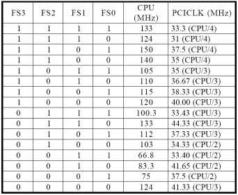
We then obtained the datasheet for the ICS 9248DF-39 clock generator
used on the P2B-AE to assist us in determining where pullup resistors
would be required in order to enable FSB selection via DIP switches.
The FSB settings table for this chip is reproduced below:

On examining the rows corresponding to currently supported FSB
speeds (66Mhz and 100Mhz), we learn that FS0 and FS1 pullup resistors
must be present, since these signals are logic '1' for both 66Mhz and
100Mhz FSB. Similarly, FS3 must be pulled down since it is logic '0'
for both supported FSB speeds - this will need correcting. FS2 is the
only FSB input which changes value between 66Mhz and 100Mhz FSB,
therefore it must be controlled by BSEL0 - we'll need to change that
too.
We also need to consider AGP to FSB bus speed ratio selection, which
should be 1:1 for 66Mhz FSB and 2:3 for 100Mhz - presumably Asus has
also arranged for this to be controlled via BSEL0 since there is no
jumper or switch provided. We plan to add an AGP ratio switch, so we
need to locate the connection between BSEL0 at the processor slot and
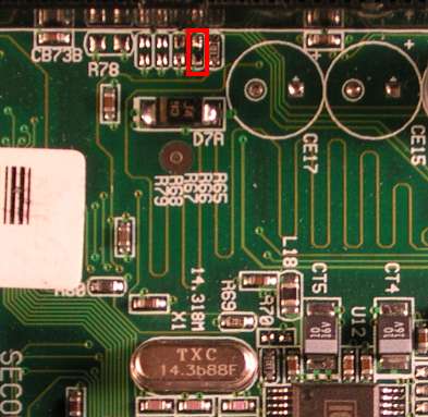
the FSB/AGP selection logic. We accomplish this by probing the
motherboard with a DMM set to diode test mode, and determine that
disconnecting BSEL0 requires removing R66:

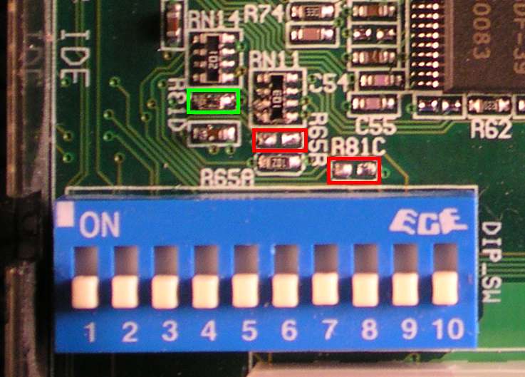
Next we remove the original 5-way DIP switch package and replace it
with a 10-way DIP switch package to provide an additional 5 switches
for AGP frequency ratio selection and FS[0-3] FSB selection, and
re-arrange resistors as required to enable the new switches to function
as desired:

We removed zero ohm resistor R81C (outlined in red above), which was
used to pull FS3 to logic '0'. We also removed 1K ohm resistor R65B
(also outlined in red), which was used to couple BSEL0 to the 440BX
chipset AGP frequency selection input. Finally, we re-used the 1K ohm
resistor removed from R65B in position R81D (outlined in green above)
to provide pullup for FS2.
To summarise the modification:
Last updated April 10, 2005 by p2b@sympatico.ca