We suspected the problem related
to routing of the bus request (SMP)
signals on the adapter, so tried covering pin B75 (BR1#) on the Slot-T
edge connector with tape, preventing it from making a connection to the
slot 1 connector on the mainboard. This allowed the system to boot with
a PIII-S processor and Slot-T adapter in slot 2. This result proved our
suspicion was correct, as the system would only boot slot 2 when the
processor could not 'see' the bus request signal.
| The
BPRI# (Bus Priority Request)
signal is used to arbitrate for ownership of the processor system bus.
It connects the appropriate pins of all processor system bus agents -
chipset and CPU(s). Observing BPRI# active (as asserted by the priority
agent) causes all other agents to stop issuing new requests, unless
such requests are part of an ongoing locked operation. The priority
agent keeps BPRI# asserted until all of its requests are completed,
then releases the bus by deasserting BPRI#. The BR0# and BR1# (Bus Request) pins drive the BREQ[1:0]# signals in the system. The BREQ[1:0]# signals are interconnected in a rotating manner to individual processor pins. During power-up configuration, the chipset asserts the BR0# bus signal. The CPUs sample their BR[1:0]# pins on active-to-inactive transition of RESET#. The pin on which the CPU samples an active level determines its symmetric agent ID. All agents then configure their pins to match the appropriate bus signal protocol, as shown below.
Our pin-taping test showed there is a problem with the BR1# signal during power-up configuration, and the Intel datasheets show the Agent IDs differ between PIII Slot 1 and PIII-S processors, but this does not explain why the S370-DL adapter works in slot 2 but the Slot-T does not. |
We then probed both the S370-DL and
Slot-T adapters with a DMM in an effort to determine how the BR1#
signal was connected. As expected, we found a connection from Pin B75
(BR1#) on the edge connector to Pin X2 (also BR1#) on the 370 pin CPU
socket. The S370-DL has a 56 ohm pullup resistor from BR1# to Vtt, but
the Slot-T does not. This difference was expected as Intel specifies a
pullup resistor for Coppermine S370 processors, but it is incorporated
on the processor substrate of Tualatin processors and therefore not
required. We tried adding a pullup resistor to the Slot-T anyway, but
as expected it did not solve the problem.
The breakthrough came when we received a
pair of PowerLeap PL-P3/SMP adapters from PowerLeap during their beta
testing program for the product. These adapters have a jumper which
allows either S370 Pin X2 (BR1#), or S370 Pin N33 (Reserved) to be
connected to Slot 1 Pin B75 (BR1#) - and we found that either jumper setting allowed dual
PIII-S processors to boot on the P2B-DS. We searched Intel datasheets
extensively, but could find no reference to S370 Pin N33 other than the
'Reserved for future use' designation - apparently Powerleap has access
to unpublished information.
We decided to try using S370 Pin N33 for
BR1# on the Slot-T adapters since it works on the PowerLeaps - and
found that Upgradeware had made this an easy modification to perform.
Instead of a jumper, they used a 0 ohm resistor in series with the BR1#
signal, and provided an unpopulated resistor site to allow rerouting of
BR1# to S370 Pin N33. All we have to do is move the 0 ohm resistor.
 |
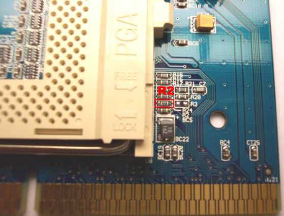
Upgradeware manufactures the Slot-T with a 0 ohm resistor in position R2. This location connects the BR1# signal from pin B75 on the edge connector to pin X2 on the CPU socket. The 0 ohm resistor is removed using a chisel tip across the length of the resistor so the solder melts at both ends simultaneously. Once the solder flows, the resistor can be picked up with tweezers. Care must be taken not to overheat the resistor or the metal ends may separate from the body - an iron temperature of 450F works well. |
 |
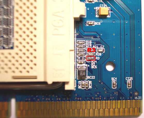
Moving the 0 ohm resistor to position R3 connects the BR1# signal from pin B75 on the edge connector to pin N33 on the CPU socket. The 0 ohm resistor is resoldered into position R3 using a fine pointed tip, again at a temperature of approximately 450F. The PCB pads for R3 may have solder left on them during the manufacturing process, which can make positioning the resistor difficult. If neccessary, the pads can be cleaned with solderwick and prepared with liquid flux prior to soldering the resistor in place. |
Last updated October 27th, 2005 by p2b@sympatico.ca